


IAMMETER Wi-Fi energy meters can send measurement data directly to a server, MQTT broker or data platform controlled by the customer. This lets developers and system integrators build their own EMS, BMS, IoT service, database or monitoring dashboard without using IAMMETER-Cloud as the data destination.
This guide approaches the integration from the receiving-server side:
IAMMETER meter
      │
      │ HTTP/HTTPS, MQTT/MQTTS or TCP/TLS
      ▼
Customer ingestion service
      │
      ├── Raw-payload log
      ├── Time-series or relational database
      ├── EMS / BMS / ERP
      └── Dashboard, report and alarm services
For meter-side firmware capabilities and address formats, use the IAMMETER Local API and Open Interface Guide. For architecture selection, see Develop Your Own Energy Monitoring System.
The meter can push its measurements using several transports. The receiving system should select one primary ingestion path.
| Transport | Receiver component | Good starting point for |
|---|---|---|
| HTTP / HTTPS | Web endpoint | REST backends and the simplest first integration |
| MQTT / MQTTS | MQTT broker and subscriber | Existing IoT platforms and message pipelines |
| TCP / TLS | Socket listener | Dedicated collectors and custom protocol services |
HTTP is normally the easiest way to inspect the first payload because the official test receiver can be started with a small Node.js example. MQTT is a strong choice when a broker is already part of the system. TCP/TLS provides a lower-level socket integration but requires more receiver-side engineering.
The secure transports and custom-port formats are maintained in the current firmware guide, rather than repeated here.
IAMMETER provides an official Node.js HTTP receiver example for integration testing.
Download the example from:
Run:
node Server.js
The example listens on port 8000. When a request arrives, it:
200 with a small success JSON response.The example is deliberately minimal. It does not provide authentication, persistence, validation, rate limiting or production security.
Before configuring the meter, confirm that:
For a LAN test, the meter and receiver can use the same local network without Internet access. For a remote receiver, the site must have a route to the server.
In the current meter WebUI, select the HTTP run mode and enter a destination such as:
{server-address}:8000/upload
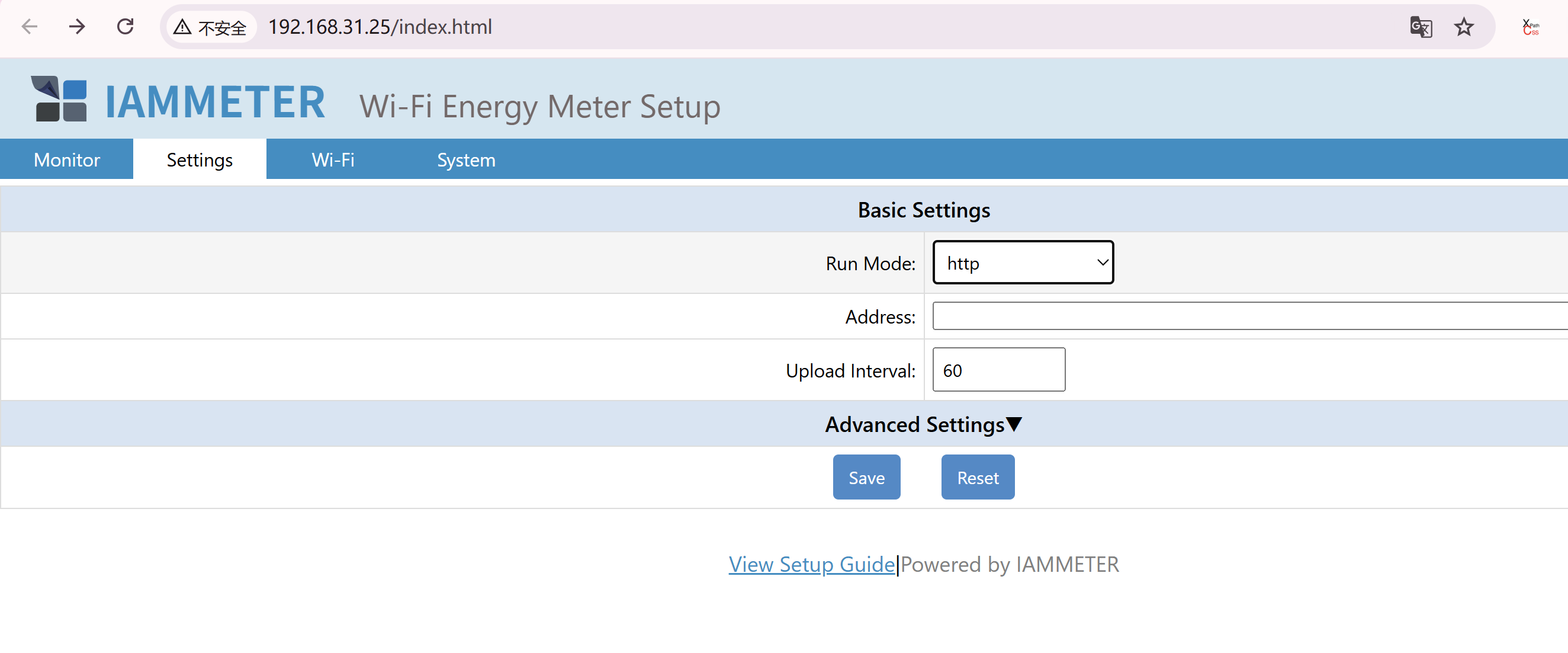
HTTPS endpoints can use the default port or a custom port. Current address rules, including https://host:port, are documented in the HTTP/HTTPS firmware section.
After saving the setting, check the receiver console for the request path and uploaded JSON. Keep this first raw payload as a test fixture for later parser and database tests.
IAMMETER uses a consistent core measurement JSON structure across the supported push transports. The transport changes how the payload arrives, but the measurement model remains consistent.
A payload normally includes device-level fields such as:
SN — meter serial number used to identify the device;version — meter firmware version;method — message method or payload type;Data or Datas — measurement arrays.Data is used for a single measurement channel. Datas contains multiple measurement arrays for a multi-channel or three-phase meter.
Example single-channel structure:
{
  "method": "uploadsn",
  "mac": "B0F8932A295C",
  "version": "i.75.98.71y",
  "server": "em",
  "SN": "12345678",
  "Data": [228.91, 1.61, 225, 15066.47, 0]
}
Do not hard-code one array count for every meter. The number of channels and available fields depends on the meter model and enabled measurement features.
Use the authoritative definition when implementing the parser:
Keep model-specific processing separate from the transport receiver.
For example, WEM3046T and WEM3046TE measure the 5 A secondary output of an external current transformer. Their values must be converted with the applicable CT ratio to obtain the primary-side measurement. This is a meter and CT characteristic, not an HTTP, MQTT or TCP difference.
A practical ingestion pipeline therefore separates:
Store enough information to reproduce and diagnose the original reading.
A useful minimum model includes:
| Field | Purpose |
|---|---|
| Meter SN | Maps the payload to a registered device |
| Channel or phase index | Distinguishes single, split-phase and three-phase data |
| Server receive time | Provides a consistent ingestion timestamp |
| Voltage | Electrical measurement |
| Current | Electrical measurement |
| Active power | Real-time import/export or load calculation input |
| Import kWh | Cumulative imported energy |
| Export kWh | Cumulative exported energy |
| Firmware version | Supports troubleshooting and parser compatibility |
| Raw payload | Allows replay, auditing and parser correction |
Additional fields such as frequency, power factor and reactive measurements should be stored when the selected model and configuration provide them.
For production systems, consider keeping:
This makes it easier to correct parsing or CT-ratio logic without losing the original payload.
Record the time at which the server accepted the payload. If the business system also uses a device or source timestamp, store both values separately rather than replacing one with the other.
Network delay, reconnects and queued processing can make ingestion time different from measurement time. Define the timestamp used by charts, billing and alarms before production deployment.
For MQTT ingestion, the customer system provides:
IAMMETER publishes real-time data under a device topic such as:
device/{SN}/realtime
Use the dedicated guide for broker configuration, credentials, topics and MQTTS considerations:
Home Assistant MQTT Discovery is not required for a general customer-server integration.
IAMMETER provides a minimal Node.js TCP listener:
The example listens on port 8000 and prints received data. A production TCP receiver must additionally provide:
Do not assume that one socket data event always equals one complete application message.
The official TLS example demonstrates a TLS listener with a server key and certificate:
Before production use, replace demonstration certificates and settings with the organization's approved certificate, key-management and security configuration. The receiver should log TLS failures separately from payload-validation failures.
The meter-side address formats for TCP and TLS are maintained in the firmware interface guide.
Current firmware supports a third-party upload interval down to 2 seconds. A short interval is useful only when the receiving system, storage and application need the additional resolution.
Approximate records generated per meter:
| Upload interval | Records per meter per day | 100 meters per day | 1,000 meters per day |
|---|---|---|---|
| 60 seconds | 1,440 | 144,000 | 1,440,000 |
| 10 seconds | 8,640 | 864,000 | 8,640,000 |
| 2 seconds | 43,200 | 4,320,000 | 43,200,000 |
These numbers represent upload events, not necessarily database rows. A three-phase payload may be normalized into several channel records, and indexes, raw-payload retention or replicated storage increase the actual database volume.
Capacity planning should include:
For one-second control or automation on the same LAN, consider Modbus TCP instead of using a remote upload pipeline.
A production receiver should expect network and application failures.
Validate at least:
Keep malformed payloads in a controlled diagnostic path without allowing them to block valid devices.
Do not assume that every interval produces exactly one permanently stored record. Network interruptions, reconnect behavior, server retries or application processing can produce missing or repeated ingestion events.
Define how the business system will:
Monitor more than the web or socket process. Useful signals include:
For an Internet-facing receiver:
Review the current MQTTS, TLS and HTTPS firmware behavior in the firmware and open-interface guide before selecting a security design.
The original version of this document focused on configuring older meter firmware. These screenshots are retained only for users identifying an existing installation. For new integrations, use the current WebUI and latest firmware.
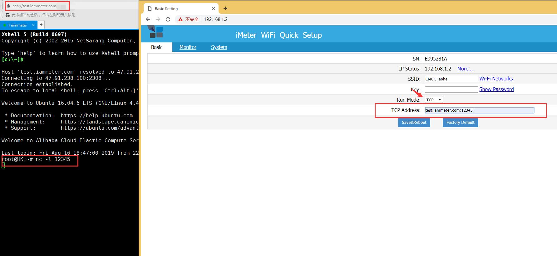
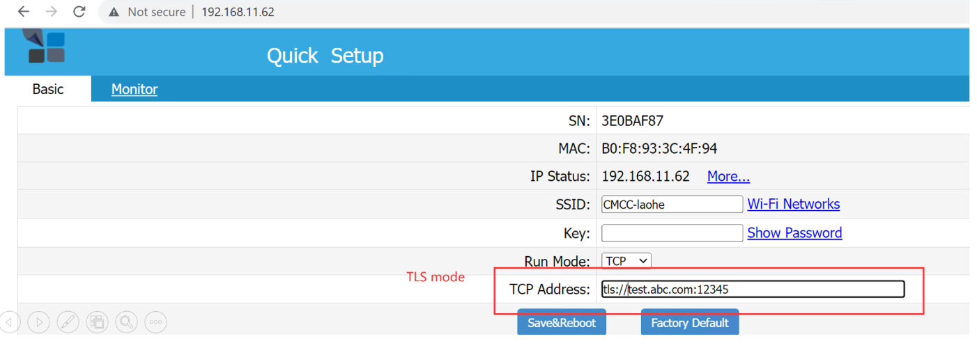
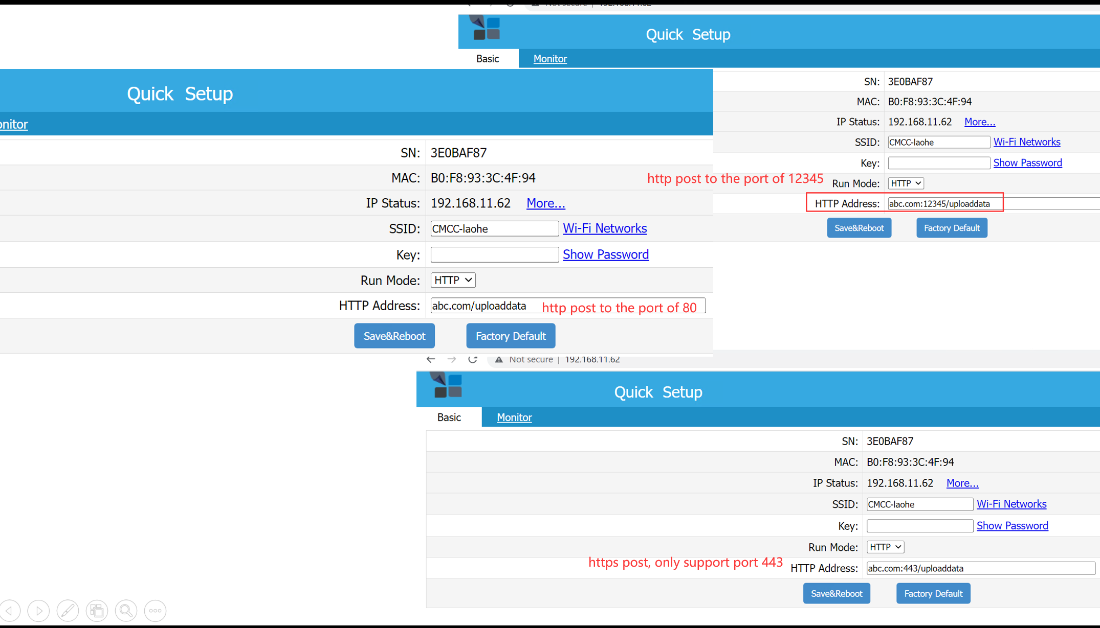
Earlier firmware documentation also used the local /api/uploadinterval configuration method and described a six-second minimum. Current firmware exposes the interval in the WebUI and supports a documented minimum of 2 seconds.
Last updated: July 16, 2026
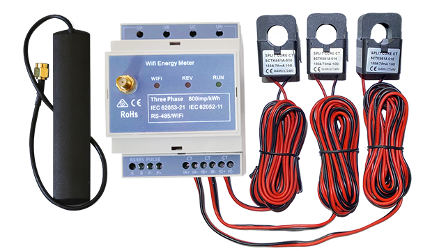
Three Phase Wi-Fi Energy Meter (WEM3080T)
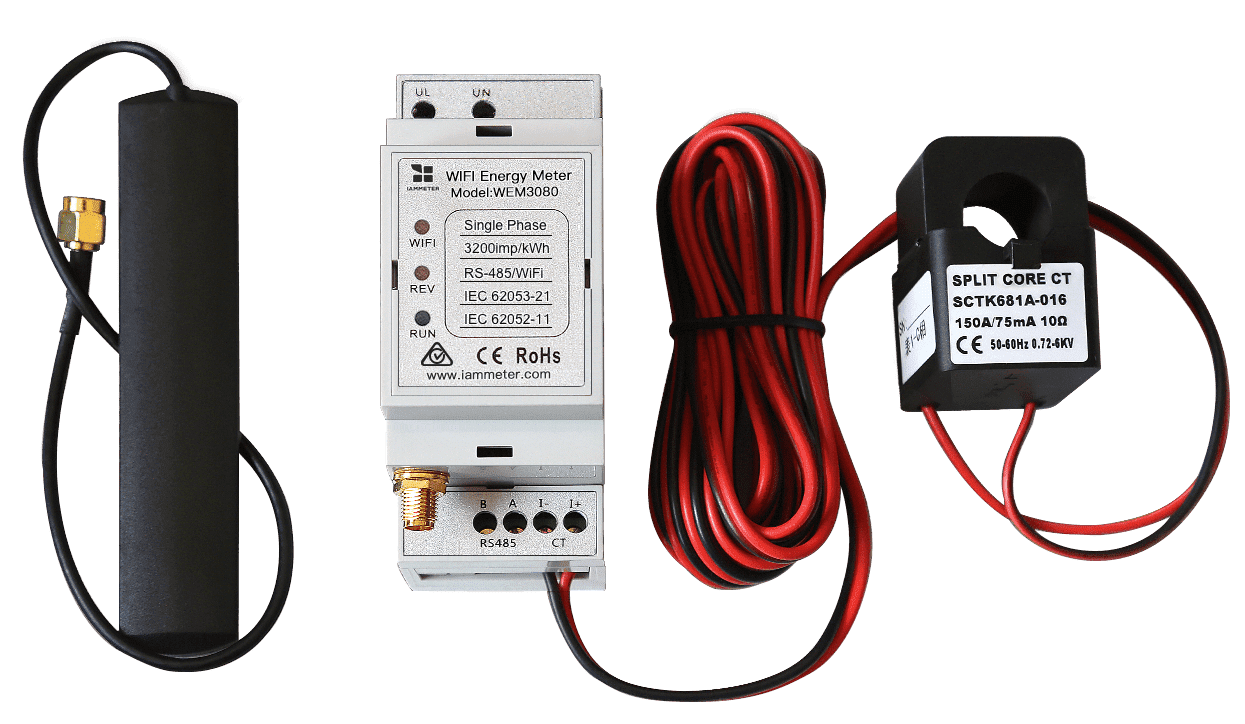
Single Phase Wi-Fi Energy Meter (WEM3080)
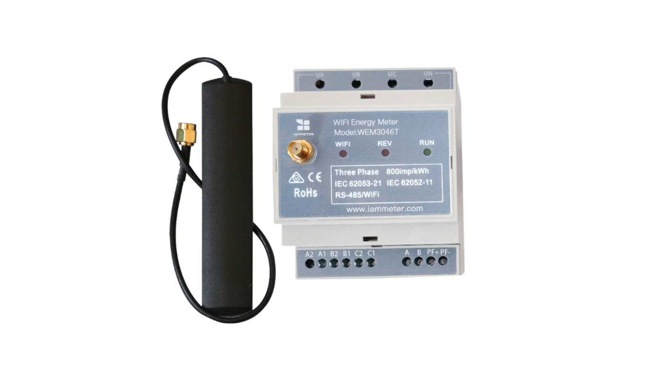
Three Phase Wi-Fi Energy Meter (WEM3046T)
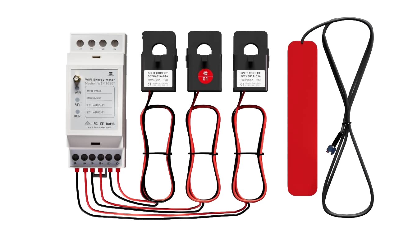
Three Phase Wi-Fi Energy Meter (WEM3050T)