


A reliable home electricity monitoring setup starts before the meter is installed. First define what must be measured, then select the correct residential meter and CT positions. After installation, validate the readings before using them as a baseline for cost or energy-saving decisions.
This guide focuses on residential system design and measurement validation. It does not repeat the standard wiring, Wi-Fi and account-registration procedure.
For electrical safety, basic wiring, Wi-Fi configuration, IAMMETER-Cloud registration, LED indicators and general troubleshooting, follow the IAMMETER Product Quick Start.
Begin with the question the monitoring system needs to answer.
Measure the conductors supplying the complete home when the goal is to track:
A split-phase residential supply has two live conductors. Both must be measured to obtain the complete home total.
Two measurement channels can be used when the homeowner wants to compare total consumption with one important load, such as a water heater, heat pump or EV charger.
The dedicated channel measures that circuit directly. The whole-home channel still contains the circuit as part of the total, so the two channels must not simply be added together.
For a single-phase grid and a single-phase inverter, one channel can measure grid import/export and the other can measure inverter AC output. IAMMETER can then calculate home consumption and solar self-consumption.
See the WEM2067 Home Solar monitoring method for the complete scenario.
A three-phase residential supply requires all three phases to be measured. Each CT channel must correspond to the correct voltage phase.
IAMMETER's primary residential choices are:
| Residential system | Measurement requirement | Recommended model |
|---|---|---|
| Single-phase whole home | One supply conductor | WEM3080 |
| Split-phase whole home | Two live conductors | WEM2067 |
| Single-phase home with two measurement points | Whole home plus one circuit, or grid plus inverter output | WEM2067 |
| Three-phase home | L1, L2 and L3 | WEM3050T |
Other IAMMETER three-phase and CT-operated models are intended for commercial or industrial applications and are not the primary choices in this residential guide.
For product selection, system boundaries and purchasing information, see the Home Energy Monitoring Solution.
The CT position determines what the meter can see.
| CT position | Data represented |
|---|---|
| Main incoming supply | Total home electricity flow at that point |
| One branch circuit | Only the load connected to that circuit |
| Solar inverter AC output | Inverter generation |
| Grid connection in a solar system | Import from and export to the utility grid |
Before installation, confirm that:
A CT must not surround the live and neutral conductors together. Their magnetic fields cancel, producing a reading close to zero.
Use WEM3080 to measure the main live conductor supplying the home. All loads that need to be included must be downstream of the measurement point.
Use both WEM2067 channels to measure the two live conductors. The total home consumption is obtained from the two channels together.
Do not use only one channel for a complete split-phase total. Loads connected to the other line would be missing.
In a single-phase home, WEM2067 can use:
This allows the dedicated load to be compared with the whole-home trend. Remember that the dedicated load is already included in the whole-home total.
WEM2067 can use:
Follow the complete WEM2067 solar wiring diagram, including the specified CT direction.
Use WEM3050T to measure L1, L2 and L3. The CT connected to each meter channel must be installed on the conductor corresponding to that channel's voltage phase.
Incorrect CT-to-phase pairing can produce incorrect power and power-factor results even when voltage and current values appear plausible.
For model-specific terminals and installation diagrams, use the IAMMETER wiring guide.
After the measurement plan is confirmed, use the authoritative Product Quick Start to complete:
Do not reproduce or improvise terminal wiring from this planning guide. Always use the diagram for the exact meter model.
After the meter reports data, check the settings that affect residential reports.
Set the correct site time zone so that daily totals and tariff periods align with local time.
Configure the tariff used to estimate electricity cost. If the utility uses time-of-use pricing, confirm the start and end time of every rate period.
Set the billing-cycle start date to match the utility bill when the cycle does not begin on the first day of the month.
Confirm that the site configuration matches the actual measurement topology. A consumption-only home, a split-phase home and a home solar system use the channels differently.
Do not assume that visible numbers are correct. Perform a controlled validation after installation.
Before switching a test load, record:
Choose a reasonably stable load with a known approximate rating, such as a heater or kettle.
The device rating and meter reading will not always be identical, but the direction and approximate change should be reasonable.
Leave a stable load running long enough to produce a visible energy increase. Confirm that accumulated kWh increases on the expected channel and in the expected direction.
For a consumption-only home, normal imported power should use the expected positive direction.
For a solar system, verify separately that:
For split-phase and three-phase homes:
When comparing IAMMETER with a utility meter or another device, use the same start and end time and the same measurement boundary. Small differences can arise from sampling, accuracy class and rounding; large differences usually require checking CT placement, phase pairing or the comparison period.
After validation, collect a baseline before making changes.
A useful first baseline is at least seven days and should include both weekdays and a weekend. For a more stable comparison, use 28 days when practical.
Record:
When testing an energy-saving change:
See Energy Consumption Analysis for reporting and comparison examples.
| Symptom | Likely cause | What to check |
|---|---|---|
| Power is close to zero even when loads are running | CT surrounds live and neutral together, or the wrong conductor | Place the CT around one intended conductor only |
| Power has the wrong sign | CT direction is reversed | Compare the CT arrow/direction with the model wiring guide |
| A known load does not change the reading | CT is installed on a different supply or branch | Trace the conductor and confirm the measurement boundary |
| Split-phase total appears too low | Only one live conductor is measured | Confirm that both WEM2067 channels are installed and reporting |
| One three-phase channel produces implausible power | CT and voltage phases do not correspond | Check L1/L2/L3 channel pairing |
| Solar import/export is reversed | Grid CT direction is incorrect | Follow the solar wiring diagram and repeat direction validation |
| Calculated solar home consumption is implausible | Grid/inverter channel role or CT direction is incorrect | Validate both channels independently |
| Daily totals reset at the wrong local time | Incorrect time zone | Check the site time-zone setting |
| Estimated bill differs substantially | Tariff, currency, billing date or comparison period is wrong | Verify every billing setting and compare identical periods |
| Cloud data is missing | Wi-Fi, Internet access or device registration issue | Follow the Product Quick Start network and LED troubleshooting |
Once the measurements are validated, choose how the data will be used:
The measurement plan and validation principles remain the same regardless of the platform receiving the data.
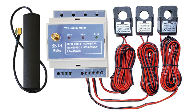
Three Phase Wi-Fi Energy Meter (WEM3080T)
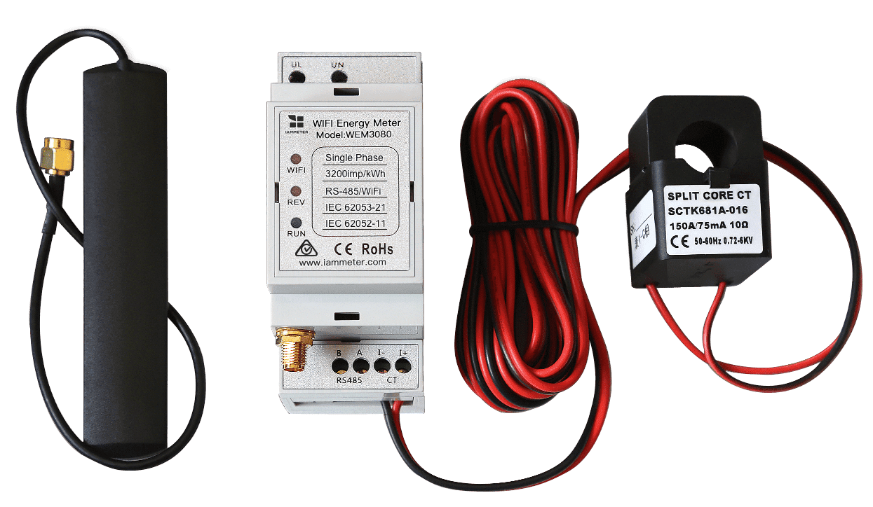
Single Phase Wi-Fi Energy Meter (WEM3080)
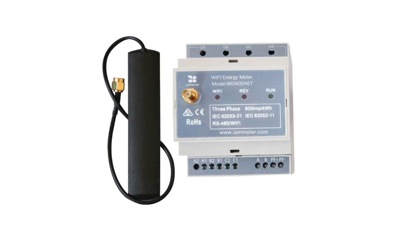
Three Phase Wi-Fi Energy Meter (WEM3046T)
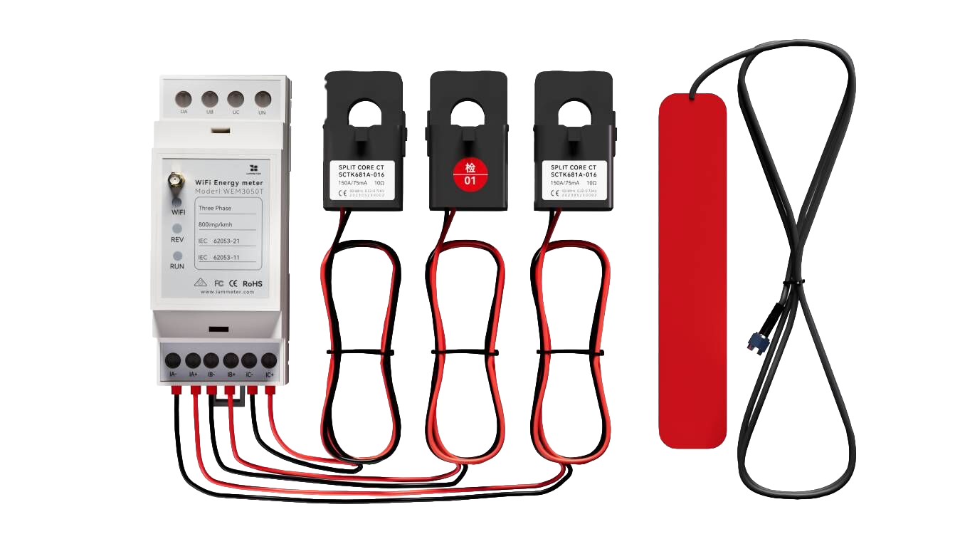
Three Phase Wi-Fi Energy Meter (WEM3050T)