


Modbus TCP Energy Meter Integration: Registers and Testing
Modbus TCP Energy Meter Integration for Local Monitoring
Modbus TCP lets a local application read electrical measurements directly from an IAMMETER Wi-Fi energy meter.
It is suitable for:
- PLC and SCADA systems;
- Home Assistant and Node-RED;
- local Energy Management Systems (EMS);
- Building Management Systems (BMS);
- one-second monitoring and automation;
- applications that must operate without IAMMETER-Cloud.
IAMMETER energy meter
        │
        │ Wi-Fi / LAN
        │ Modbus TCP
        ▼
Home Assistant, Node-RED, PLC, SCADA or custom EMS
The client initiates each request. The meter returns register values for voltage, current, active power, imported energy, exported energy, power factor, frequency and other supported measurements.
Modbus TCP is a local polling interface. If the meter should publish data to a broker, use MQTT. If it should upload data to a customer server, see Receive IAMMETER Data on Your Own Server.
1. Why Use Modbus TCP?
Compared with cloud polling or periodic meter uploads, Modbus TCP provides:
- direct access over the local network;
- no dependency on IAMMETER-Cloud for the data path;
- a standard register-based interface;
- one-second polling for supported applications;
- signed active-power values for bidirectional energy monitoring;
- compatibility with common automation and industrial tools.
Typical uses include:
- controlling a load from real-time grid power;
- reading solar production, grid exchange or circuit load locally;
- adding an energy meter to Home Assistant;
- collecting measurements in Node-RED;
- integrating electricity data into a PLC, SCADA, EMS or BMS.
2. Supported IAMMETER Meters
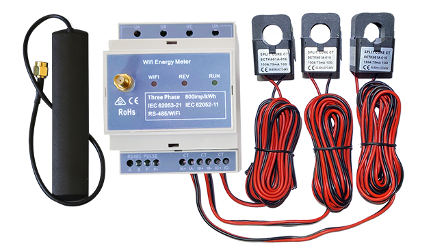
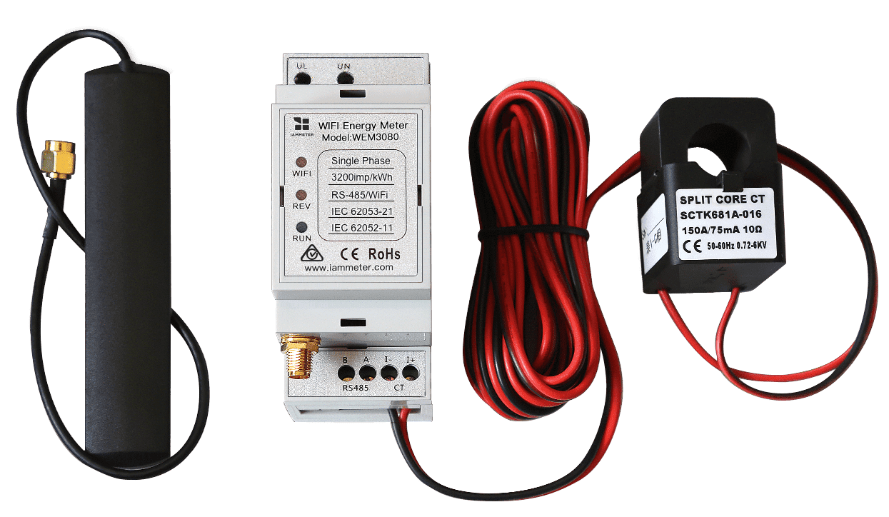
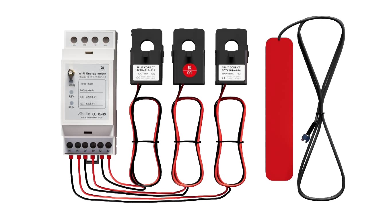
Current IAMMETER energy meter models support the available Home Assistant and open-integration modes, including Modbus TCP. The discontinued WEM3162 is not considered in this guide.
The main difference between models is the number and purpose of measurement channels:
- single-channel meters expose the Phase A register block;
- dual-channel or split-phase meters use the applicable channel blocks;
- three-phase meters expose Phase A, B and C blocks;
- supported meters may also expose totals and optional reactive measurements.
Always validate the register response against the exact model and firmware used in the project.
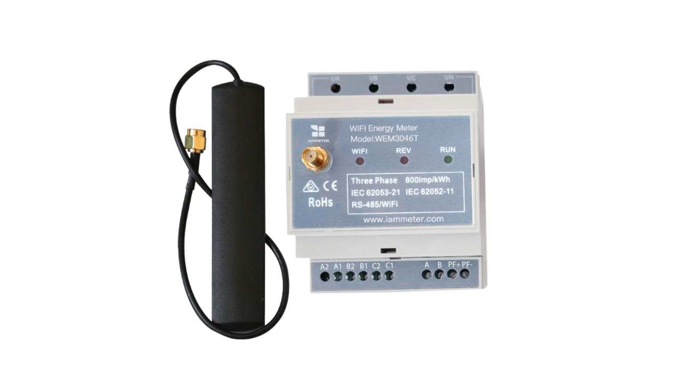
WEM3046T and WEM3046TE
WEM3046T and WEM3046TE measure the 5 A secondary output of an external current transformer.
The primary-side current, power and energy values must therefore use the applicable external CT ratio. This scaling requirement is caused by the 5 A CT input design of the meter; it is not a Modbus TCP or platform-specific behavior.
Keep CT-ratio processing documented and tested wherever these models are integrated.
3. Connection Parameters
The official IAMMETER Modbus Poll example uses:
| Parameter | Example value |
|---|---|
| Connection | Modbus TCP/IP |
| Host | Local IP address of the meter |
| TCP port | 502 |
| Device / Unit ID | 1 |
| Function code | 03 — Read Holding Registers |
| Response timeout | 1000 ms in the example |
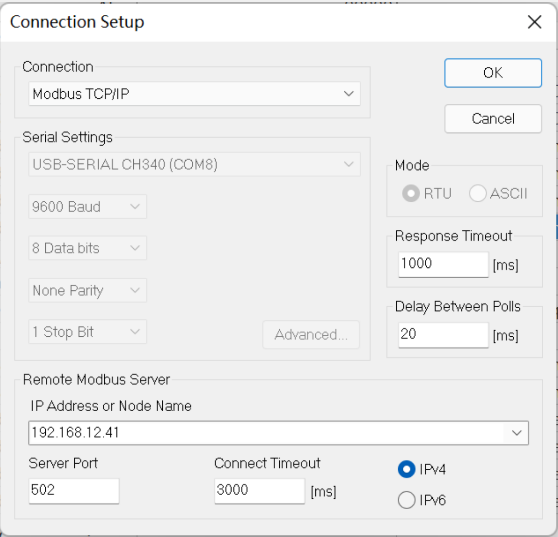
Use the meter's LAN IP address as the host. Reserving the address in the router can prevent an integration from breaking after a DHCP address change.
The values above are the parameters shown in the official example. Confirm the actual firmware and site configuration before hard-coding them in production software.
4. Quick Test with Modbus Poll
To confirm connectivity before configuring a complete platform:
- connect the computer and IAMMETER meter to the same LAN;
- find the meter's local IP address;
- create a Modbus TCP/IP connection to port
502; - set Device ID to
1; - select Function Code
03; - request holding registers beginning at address
0; - compare the returned raw values with the scaling rules below.
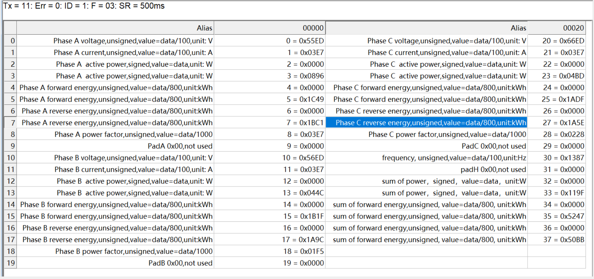
The screenshot uses a 500 ms display scan rate for testing. For normal use, IAMMETER documentation recommends one-second polling rather than treating the fastest client setting as the supported production interval.
If the connection fails, check:
- that the meter and client are on the same reachable network;
- the meter IP address;
- TCP port 502 and firewall rules;
- Device ID and function code;
- whether another application is already controlling the intended polling workflow;
- the meter firmware version.
5. Register Data Types and Scaling
IAMMETER uses 16-bit holding registers.
16-bit values
Voltage, current, power factor and frequency use one register:
| Measurement | Raw type | Conversion |
|---|---|---|
| Voltage | Unsigned 16-bit | V = raw / 100 |
| Current | Unsigned 16-bit | A = raw / 100 |
| Power factor | Unsigned 16-bit | PF = raw / 1000 |
| Frequency | Unsigned 16-bit | Hz = raw / 100 |
32-bit values
Active power, cumulative energy and reactive values use two consecutive registers.
The official Modbus Poll example displays the high-order 16-bit word first. Combine the words as:
raw32 = (register[n] << 16) | register[n + 1]
Interpret active and reactive power as signed 32-bit values. Interpret cumulative energy pulse counters as unsigned 32-bit values.
| Measurement | Raw type | Conversion |
|---|---|---|
| Active power | Signed 32-bit | W = raw32 |
| Import/forward energy | Unsigned 32-bit | kWh = raw32 / 800 |
| Export/reverse energy | Unsigned 32-bit | kWh = raw32 / 800 |
| Reactive power | Signed 32-bit | var = raw32 |
| Inductive/capacitive reactive energy | Unsigned 32-bit | kvarh = raw32 / 1000 |
Signed active power allows an integration to distinguish opposite power directions. Confirm the sign convention against the CT orientation and application wiring during commissioning.
6. Core Modbus Register Map
Register addresses below are decimal offsets. The client should use Function Code 03.
Phase A
| Address | Length | Measurement | Conversion |
|---|---|---|---|
| 0 | 1 | Voltage | Unsigned, /100 V |
| 1 | 1 | Current | Unsigned, /100 A |
| 2 | 2 | Active power | Signed, W |
| 4 | 2 | Import/forward energy | Unsigned, /800 kWh |
| 6 | 2 | Export/reverse energy | Unsigned, /800 kWh |
| 8 | 1 | Power factor | Unsigned, /1000 |
| 9 | 1 | Model identifier in the legacy map | Do not use as the sole current model catalog |
Phase B
| Address | Length | Measurement | Conversion |
|---|---|---|---|
| 10 | 1 | Voltage | Unsigned, /100 V |
| 11 | 1 | Current | Unsigned, /100 A |
| 12 | 2 | Active power | Signed, W |
| 14 | 2 | Import/forward energy | Unsigned, /800 kWh |
| 16 | 2 | Export/reverse energy | Unsigned, /800 kWh |
| 18 | 1 | Power factor | Unsigned, /1000 |
| 19 | 1 | Reserved | Not used |
Phase C
| Address | Length | Measurement | Conversion |
|---|---|---|---|
| 20 | 1 | Voltage | Unsigned, /100 V |
| 21 | 1 | Current | Unsigned, /100 A |
| 22 | 2 | Active power | Signed, W |
| 24 | 2 | Import/forward energy | Unsigned, /800 kWh |
| 26 | 2 | Export/reverse energy | Unsigned, /800 kWh |
| 28 | 1 | Power factor | Unsigned, /1000 |
| 29 | 1 | Reserved | Not used |
Frequency and totals
| Address | Length | Measurement | Conversion |
|---|---|---|---|
| 30 | 1 | Frequency | Unsigned, /100 Hz |
| 31 | 1 | Reserved | Not used |
| 32 | 2 | Total active power | Signed, W |
| 34 | 2 | Total import/forward energy | Unsigned, /800 kWh |
| 36 | 2 | Total export/reverse energy | Unsigned, /800 kWh |
The total registers are most relevant to multi-channel meters. For a single-channel integration, use the applicable Phase A values and validate any returned totals.
7. Optional Reactive Registers
Reactive registers are available only when reactive measurement is supported and enabled by the applicable meter and firmware.
| Address | Length | Measurement | Conversion |
|---|---|---|---|
| 38 | 2 | Phase A reactive power | Signed, var |
| 40 | 2 | Phase A inductive reactive energy | Unsigned, /1000 kvarh |
| 42 | 2 | Phase A capacitive reactive energy | Unsigned, /1000 kvarh |
| 44 | 2 | Phase B reactive power | Signed, var |
| 46 | 2 | Phase B inductive reactive energy | Unsigned, /1000 kvarh |
| 48 | 2 | Phase B capacitive reactive energy | Unsigned, /1000 kvarh |
| 50 | 2 | Phase C reactive power | Signed, var |
| 52 | 2 | Phase C inductive reactive energy | Unsigned, /1000 kvarh |
| 54 | 2 | Phase C capacitive reactive energy | Unsigned, /1000 kvarh |
Do not assume these values are active on every installation. Confirm the model, firmware and reactive-measurement setting.
8. Device Information Registers
| Address | Length | Description |
|---|---|---|
| 56 | 8 | Device serial number |
| 64 | 1 | Runtime in seconds |
Treat serial numbers and other device identifiers as operational data. Avoid publishing unsanitized values in screenshots, logs or public examples.
9. Integration Examples
Home Assistant
Modbus TCP is the IAMMETER Home Assistant option for users who need fast local readings and automation.
Use the IAMMETER Home Assistant integration guide as the main HA entry. It separates meter-side configuration from Home Assistant configuration and links to the current Modbus implementation methods.
Video:
Node-RED
Node-RED can poll the holding registers, normalize the raw values and route the measurements to automation flows, databases or dashboards.
PLC, SCADA, EMS and BMS
For an industrial or commercial integration:
- document the register map version used;
- apply the correct signed/unsigned conversion;
- validate byte and word order;
- confirm CT orientation and CT ratio;
- define timeout and retry behavior;
- monitor the last successful poll;
- avoid unsupported polling rates;
- test network interruption and recovery.
Custom software
A custom Modbus TCP client should separate:
- connection and retry logic;
- register reads;
- 16-bit and 32-bit decoding;
- meter-model and channel mapping;
- CT-ratio normalization where required;
- storage and application logic.
10. Modbus TCP or Another IAMMETER Interface?
| Requirement | Recommended interface |
|---|---|
| One-second local polling | Modbus TCP |
| Simple JSON retrieval over the LAN | Local HTTP API |
| Publish data to multiple consumers | MQTT |
| Meter uploads to a customer web service | HTTP/HTTPS |
| Meter uploads to a custom socket server | TCP/TLS |
| Ready platform comparison | Open-source integration guide |
Related guides:
- IAMMETER Local APIs and Open Interfaces
- Open-Source Energy Monitoring Platforms
- Develop Your Own Energy Monitoring System
- Use IAMMETER Without Internet or Cloud
11. Firmware
Modbus TCP is no longer an experimental upgrade described only by the original 2022 release process. For a current installation, use the latest firmware available for the meter model:
Record the firmware version used to validate the register map and polling behavior.
12. Legacy Release Information
This article was originally published when Modbus TCP support was introduced through a firmware upgrade.
The older instructions referred to firmware 75.68 as an upgrade prerequisite and asked users to request an upgrade through the feedback system. That process is retained here only as historical context and should not be used for a new installation.
Original release resource:
Last updated: July 16, 2026